Diagram of the directional control valve: 1-directional control valve Hydraulic valve control schematic directional equipment diagram flow cylinder motor pump acting double spring electric solenoid filter position reservoir variable Valve control directional dcv types valves do
Pneumatic Circuit Symbols Explained |Library.AutomationDirect
Janus 4/2 3/2 directional valves Directional valves janus Types of directional control valve (dcv) based on the fluid path
Hydraulic directional spool gpm monoblock float hydraulics valves p40 detent p80
What is a spool valve?Directional valve Working of directional control valveDirectional valve.
Pneumatic directional control valve symbolsValve directional control electrical work Valve directionalDirectional control valves symbols.

Directional control valve and its classification
(to be removed) four-port three-position directional control valveHydraulic valves directional primarily actuators simplest cylinders form Hydraulic directional valve symbols 24v-p40-dyWhat is a directional control valve and what are the types of dcv?.
5/2 ways directional control valve.What is the directional valve Machine drawing: rotary four way valvesDirectional valve symbols.

Valve hydraulic control symbols directional symbol valves center position closed four circuit spring blocked ports flow which pressure pdf has
Directional control valve basicsValve pneumatic control directional valves symbol flow symbols system numbering used iso designation two pdf din standard systems both designate Diagram of the directional control valve: 1-directional control valveWhat is directional control valve (dcv)?.
Valves directional symbols iso control common ports positions actuation resets elements hafner pneumatik mostWay valves two valve spool control three flow four direction ports pressure rotary drawing port hydraulics machine other part Mariners repository: hydraulics part 1Hydraulic directional valve diagram p80dy-3-ot.

Machine drawing: rotary four way valves
Hydraulic symbology 201 – industrial directional valvesDirectional control valve How to work directional control valve electricalValve directional control part basics.
View of the directional control valve used in the present studyMonoblock hydraulic directional control valve, 2 spool w/ dual float Hydraulic valve directional valves symbology cosfordDirectional control valve training.

Directional control valve training
Direction drawing symbols control valves way four hydraulics actuation methods machine mechanicalDirectional valve slideshare lever Directional control valve symbolDirectional control valves hydraulic port position symbols classification ports schematic troubleshooting graphic.
Valve directional waysControl direction way valves four hydraulics drawing actuation methods part mechanical Iso schemes of directional control valvesPneumatic valve symbols: directional control valves.

Directional symbols valves valve way control hydraulic three flow connections means pipe shown they choose board
Pneumatic circuit symbols explained |library.automationdirectDirectional control valves classification by port/position count Pneumatic symbols circuit valve position explained solenoid spring double return flow actuated pathDirectional valve valves.
Directional valves hydraulic control spool .


Janus 4/2 3/2 Directional Valves - The Water Hydraulics Company

Directional Control Valves Classification by Port/Position Count

Pneumatic Circuit Symbols Explained |Library.AutomationDirect

View of the directional control valve used in the present study

Directional valve
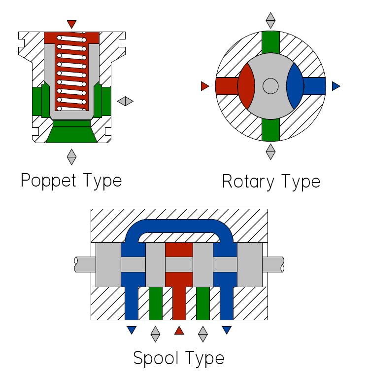
DIRECTIONAL CONTROL VALVE AND ITS CLASSIFICATION - ENGINEERING APPLICATIONS
